Search This Blog

Thursday, May 30, 2013

How to find a YouTube video on blogger.com

When you want to add a video to your blog post on http://www.blogger.com/ the search mechanism may not be able to find it on YouTube. For example try to search for string Cisco 1 - VXLAN and the Nexus 1000v with Han Yang.

Problem

How to add video from YouTube to your blog.

Solution
  • Add a random video from YouTube and copy the HTML code (example bellow)

    • <div class="separator" style="clear: both; text-align: center;"> <object width="320" height="266" class="BLOGGER-youtube-video" classid="clsid:D27CDB6E-AE6D-11cf-96B8-444553540000" codebase="http://download.macromedia.com/pub/shockwave/cabs/flash/swflash.cab#version=6,0,40,0" data-thumbnail-src="http://img.youtube.com/vi/lU1GXLSVQOk/0.jpg"><param name="movie" value="http://youtube.googleapis.com/v/lU1GXLSVQOk&source=uds" /><param name="bgcolor" value="#FFFFFF" /><param name="allowFullScreen" value="true" /><embed width="320" height="266" src="http://youtube.googleapis.com/v/lU1GXLSVQOk&source=uds" type="application/x-shockwave-flash" allowfullscreen="true"></embed></object></div>

  • Find your video id on YouTube 


  • Replace in the HTML code the 3 places with old id lU1GXLSVQOk with the new ID l4JCBq1aXKE

Wednesday, May 29, 2013

How does Nexus 1000v support VXLAN protocol

In the previous post we we explained how VXLAN works. Below is a complementary video about VXLAN from a Cisco product manager Han Yang showing a live Cisco Nexus 1000V training session.


Interesting facts that are not directly mentioned in the previous post:
  • Only one Nexus 1000V (N1V) can be deployed on a single hypervisor (multiple hypervisors have its own 1000V virtual switch)
  • Nexus 1000V has built in mechanism for loop prevention (time ~21:00)
    • if it receives a packet on the outside interface with a src MAC address that belongs to one of its attached VMs it drops it
    • it drops STP BPDU; as hypervisors are considered 'leaves' in the network topology they don't have to participate in STP 
  • As VXLAN is an L3/L4 network overlay it handles the VM generated broadcast, multicast and unknowns unicast with a help of IP multicast (time ~27:00)
  • The point above says that for example VM ARP request will be distributed to all hypervisors using IP multicast (remember that each hypervisor has its own IP; when there is a communication between hypervisors they communicate using their own IPs. The real VMs communication is encapsulated using VXLAN and is carry over in UDP datagram)
  • You don't have to have a separate multicast domain per VXLAN domain (resulting in separate multicast trees and multicast groups that a router need to managed). A single multicast can be shared by many VXLAN (time ~36:00)
  • Not sure about this: I have couple of VMs in my VXLAN that want to communicate together using IP multicast. This multicast traffic is not the same like when an ARP need to be distributed among hypervisors. This is VMs internal traffic. Will this VM IP multicast traffic be distributed to all hypervisors or only to these who actually host a relevant VM(s) that joined the VM multicast group before (IGMP snooping) (time 30:00-30:35)
  • In a single VXLAN you can have multiple customer defined VLANs (this becomes obvious when you look at the VXLAN frame headers) (time ~30:00)
  • You can tunnel VXLAN using OTV (time 45:00)
  • You need an L3 gateway device to allow traffic between traditional VLAN and VXLAN domains
  • There is an option to integrate within VXLAN network a vASA (virtual ASA) firewall

How to extract a single SSL connection from tcpdump

There is not better tool for SSL troubleshooting than ssldump (a very useful how to use in a form of F5 solution can be found here: SOL10209: Overview of packet tracing with the ssldump utility.

The ssldump tool is not perfect although. It can produce only text output. The output is a mixture of SSL handshaking requests and data connections.

This little tool https://github.com/akozadaev/ssld-extract can help to extract a single SSL session. An example usage is provided below.
root@server:~/ssld-extract/# ssldump -n -r example1.pcap  > example1.pcap.txt
root@server:~/ssld-extract/pp# python ssld-extract.py -c -n1 ~/ssld-extract/example1.pcap.txt
New TCP connection #1: 192.168.0.2(57122) <-> 72.26.232.202(443)
1 1  0.1946 (0.1946)  C>S  Handshake
      ClientHello
        Version 3.1
        resume [32]=
          7b 9a 08 2f 3f c0 5e 70 c8 9e b6 f8 61 a0 4e 9e
          d9 84 07 e5 94 13 f8 e8 87 33 96 0d f4 a4 9f 6a
        cipher suites
        Unknown value 0xc00a
        Unknown value 0xc014
        Unknown value 0x88
        Unknown value 0x87
        TLS_DHE_RSA_WITH_AES_256_CBC_SHA
        TLS_DHE_DSS_WITH_AES_256_CBC_SHA
        Unknown value 0xc012
        TLS_DHE_RSA_WITH_3DES_EDE_CBC_SHA
        TLS_DHE_DSS_WITH_3DES_EDE_CBC_SHA
...
        compression methods
                  NULL
1 2  0.3973 (0.2027)  S>C  Handshake
      ServerHello
        Version 3.1
        session_id[32]=
          d4 65 5e b6 3d 33 88 8c bd 7e 56 65 13 71 9f 52
          30 47 ea e1 c0 d6 1f 72 12 b9 2f 8f 6b 42 b2 68
        cipherSuite         TLS_RSA_WITH_RC4_128_SHA
        compressionMethod                   NULL
1 3  0.3974 (0.0001)  S>C  Handshake
      Certificate
1 4  0.3974 (0.0000)  S>C  Handshake
      ServerHelloDone
1 5  0.4006 (0.0031)  C>S  Handshake
      ClientKeyExchange
1 6  0.4006 (0.0000)  C>S  ChangeCipherSpec
1 7  0.4006 (0.0000)  C>S  Handshake
1 8  0.5794 (0.1788)  S>C  ChangeCipherSpec
1 9  0.5794 (0.0000)  S>C  Handshake
1 10 0.5814 (0.0019)  C>S  application_data
1 11 0.5819 (0.0004)  C>S  application_data
1 12 0.7806 (0.1987)  S>C  application_data
As you can see it was able to extract the single connection what is a huge help if you need to analyze a big tcpdump file.

New features in OpenStack Grizzly

There is a new Openstack released called Grizzly available. In this post I would like to share some info with you to answer the following questions:
  • What changed
  • What new features were implemented
  • What improvements were made 
Let's summarize first couple of facts we can confirm about Grizzly.
  1. For every new release there is a release note (for Grizzly here). As an example links to Nova related releases and blueprints check this Nova release notes and blueprints link.
  2. There are 2 webcasts (with video and slides) from Mirantis that discuss changes in Folsom and Grizzly.
The new video and slides from Mirantis for Grizzly are really informative: What’s new in OpenStack Grizzly. Some of the slides I found interesting for Nova and Quantum are copied below.
  • In Nova project there were many enhancements for VM placements and improvements for  large scale deployments support

  • New awaited features for network virtualization in Quantum project 

  • There were number of new vendor plugin announcements for Quantum to give people choice how to implement network virtualization. More info about Midokura (here) and Nicira (here) is available as well.

References
  1. http://rtomaszewski.blogspot.co.uk/search/label/grizzly
  2. http://rtomaszewski.blogspot.co.uk/search/label/folsom

Monday, May 27, 2013

How does the VXLAN protocol work

The VXLAN is one of the overlay network tunneling protocols that is used to built network infrastructure for cloud environment. Below are some details about the operation and specification.
  • Frame headers definition

  • The traffic between VMs is encapsulated in IP/UDP packets
  • Logical isolation is implemented in a form of logical overlay where the traffic is exchanged between encryption tunnels endpoints
  • VXLAN ID is used to identify the specify isolated L2 cloud network that belongs to a tenant
  • The tunnel endpoints represent the edge of the cloud network infrastructure
  • The tunnel endpoints perform encapsulation and decapsulation
  • It is there where all the logic is implemented to find out where to sent next a packet or to witch VM the packet should be delivered after decapsulation


  • A comprehensive summary and operational features can be found under the links in reference section, below are few of the main characteristics and benefits:
    • It operates over IP and used UDP to carry payload 
    • Multicast support is the only other requirement for switches and routers to support VXLAN 
    • Multicast is used to handle L2 broadcast traffic (like ARP requests)
    • Logical networks can be extended among virtual machines placed in different Layer 2 domains
References
  1. http://www.definethecloud.net/vxlan-deep-dive
  2. http://www.definethecloud.net/vxlan-deep-divepart-2
  3. http://www.cisco.com/en/US/prod/collateral/switches/ps9441/ps9902/white_paper_c11-685115.html
  4. http://www.emulex.com/artifacts/d658610a-d3b6-457c-bf2d-bf8d476c6a98/elx_wp_all_VXLAN.pdf
  5. http://blogs.cisco.com/datacenter/more-vxlan-qa/
  6. http://blog.scottlowe.org/2011/12/07/revisiting-vxlan-and-layer-3-connectivity/
  7. http://blog.scottlowe.org/2011/12/22/otv-and-vxlan-layer-3-connectivity-compared/

Sunday, May 26, 2013

Can Cloud load balancer use other than ServiceNet network

The are couple of network that you are going to hear when hosting physical servers and using cloud product at Rackspace. The most important one are:
  • Public network
  • ServiceNet network
  • Private cloud network
Public network is a conventional large scale, 3 tier network (built using access, distribution, core routers and switches) that forward all public traffic. There is cloud public network and there is a dedicated public network.

ServiceNet is internal network. We use the same name either you have a cloud server or a dedicated server. All your internal communication between cloud-cloud and dedicated-dedicated can or is happening over it. The dedicated ServiceNet is separated from the cloud ServiceNet even though the names are the same.

Private cloud network is an enhancement on the cloud site that allows you to create your own isolated network for the cloud tenant you created. It can be used for any  traffic you want and you can assign any subneting you wish. This network is implemented in a form of an network overlay with a help of SDN technology (Nicira).

By default all cloud servers and other cloud products will be connected to cloud ServiceNet network. That means every cloud load balancer at Rackspace can communicate with cloud server using internal network.

At the moment (May 2013) there is  no support for cloud load balancer (CLB) to sent or receive traffic from private cloud network. If you want to load balance traffic across cloud servers using CLB you have only 2 options:
  • user ServiceNet network interface (10.*)
  • use public network interface (cloud server additional bandwidth costs will be added)
The public network is not free and you need to pay for every MB you sent out (pricing).

References
  1. http://support.rightscale.com/06-FAQs/What_is_Rackspace_ServiceNet_and_how_can_I_use_it%3F
  2. http://www.rackspace.com/knowledge_center/article/rackconnect-with-cloud-networks-faq


Thursday, May 23, 2013

Midonet packet processing

The few slides below from Midokura account on slideshare.net show the internal architecture design and packet processing that is happening whey you deploy Midonet as a cloud virtualization engine.
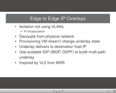
  • Midonet is based on an IP overlay concept 

  • By implementing in IP encapsulation it can provide tenant isolation and more advance features

  •  By pushing the intelligence to the edge of the network (like hypervisors) it can handle the packet forwarding efficiently with out having to consult the with any external system
  • All Midonet processes built a single logical distributed system within each single Midonet node is capable of finding and implementing the right action for a packet
  •  As an example if VM tries to communicate with a peer that doesn't belong to the tenant the verification can be done at the edge without having to sent the packet out

References
  1. http://www.slideshare.net/midokura/12th-japan-cloudstack-user-group-meetup
  2. http://www.slideshare.net/midokura/cloudstack-collab-talk
  3. http://www.slideshare.net/midokura/midonet-us-launch-oct-15-14706786

Midokura Midonet software

The network virtualization movement is getting bigger and stronger. Looking how serious the VMware is looking into SDN concept ( VMware NSX Network Virtualization ) is is only a matter of time before we start seeing this on a regular basis in data centers.

With this message in mind let's take a look at one of the SDN vendors like Midokura and its software Midonet.
  1. General availability 

  2. During Openstack Summit in April 2013 Midokura sent a strong message that its Midonet software is available to download. Midonet is Midokura the SDN implementation of the cloud network virtualization concept.

  3. Software

  4. At the moment there is only a little bit of information what it is.

    MidoNet pushes intelligence to the edge of the network, as it takes an overlay-based approach to network virtualization and sits on top of any IP-connected network. [1]

    Its technology is functionally similar to VMware-backed Nicira's, but the approach is different: Midokura has a Level 3 network gateway, whereas Nicira is Level 2. Both companies offer distributed switching at Level 2 [2]

    Midokura uses a continuous-licensing basis for its network virtualization software. The technology is a 5-to-10MB download that runs on top of a JVM on standard server hardware. [2]

  5. Midonet network architecture
  6. Below, on the left we see the logical and on the right the physical topology.

    The main logical concept is based on having a virtual router that your VMs are talking to. As Midonet software is using/is based on Open vSwitch that pacifically means that there is going to be a virtual port attached to Virtual router and VM in Open vSwitch. That way the VM is directly (virtualy) connected to its virtual router / default gateway. The building layout of the physical topology seems to confirms that assumptions.

    The physical topology help us better understanding the Midonet distributed model as well: Midonet software architecture.

    The backend network is a standard IP base physical network infrastructure that aims to provide IP connectivity between the Midonet nodes. The power of Midonet comes from the way it manages its distributed NW State DB (network state data base). This is the critical part and place where is decided what to do with an Ethernet frame/IP packet from or to VM when there is no flow entry on the routers or hypervisor virtual switches.

    This is the link for a full Midokura Midonet presentation (in Japan).


References
  1. http://www.midokura.com/press-releases/midonet_launch_at_openstacksummit2013/
  2. http://www.theregister.co.uk/2013/04/02/midokura_sdn_funding/

Wednesday, May 22, 2013

Network virtualization jargon

I've read recently this blog post Virtual Network Domain and Network Abstractions. In the post PlumGrid  CTO describes challenges and opportunities that currently exists in cloud network. In my opinion what makes it unique and interesting in comparison to other blogs concentrating on network virtualization is the language he uses.

Below are some of the examples:
  • Distributed Virtual Switch (DVS)
  • Physical Network Infrastructure (PNI)
  • Virtual Broadcast Domains (aka Distributed VLANs) 
  • Virtual Network Infrastructure (VNI)
  • Virtual Network Domains (VND)
Do you believe that these concepts are more understandable when we speak about networking in the cloud. Typically described today as network virtualization, virtual network, cloud network, hybrid network or private network.

References
  1. http://umairhoodbhoy.net/2013/02/12/what-is-plumgrid-up-to/
  2. http://en.wikipedia.org/wiki/Network_virtualization

Tuesday, May 21, 2013

Architecture frameworks

Did you see big systems implementations?
Did you participated in a system implementation or deployment?
What is your current role?
What is your carrier goal?

Every company is organised in a different way. Every company is build in a different way. But it all starts from a vision that is going to be mapped into an architecture. Once the concept or the first sketches of the architecture are established the implementation process is going to follow.

It is an example how it can look like. If you are interested in other options it is worth to take a look at some of the established (enterprise) architecture frameworks. Generally speaking, it is rather a quite difficult document to read as it tries to address the issue of an enterprise company. But even though its complexities it still gives a good overview how complex some processes, implementations or deployments can be. Below is a table from FEAF framework that list key roles and teams for an organisation.


This one below shows the concept of an architecture from a high level point of view.


The more detailed description of the architecture domains can be found here. Personally, I'm specializing in the area of technical infrastructure architecture. With the specialization in virtual networking and cloud network in IaaS cloud.

Technical architecture or infrastructure architecture: The structure and behaviour of the technology infrastructure. Covers the client and server nodes of the hardware configuration, the infrastructure applications that run on them, the infrastructure services they offer to applications, the protocols and networks that connect applications and nodes.

References
  1. http://en.wikipedia.org/wiki/Solution_architecture
  2. http://en.wikipedia.org/wiki/Architecture_domain
  3. http://en.wikipedia.org/wiki/TOGAF
  4. http://pubs.opengroup.org/architecture/togaf8-doc/arch/
  5. http://en.wikipedia.org/wiki/Multitier_architecture
  6. http://en.wikipedia.org/wiki/Peer-to-peer

Openssl cheat sheet

  • How to extract certificates
Usual certificate files have not only the certificate itself but include the chain as well.

# example chain cert file

-----BEGIN CERTIFICATE-----
687f687asfafaufyaufasfyfyasifyayfafvG74WlTANBgkqhkiG9w0BAQUFADBm
678fa6auyasfyasf8a7fa9f7a9sfiauy987safasffQgSW5jMRkwFwYDVQQLExB3
....
UW9iatnbVzOcOdJJaBK7obGALVFBAQ==
-----END CERTIFICATE-----
-----BEGIN CERTIFICATE-----
76af5at7fat8f7astfuyasftuftauftaufasfasfOzANBgkqhkiG9w0BAQUFADBs
....
tfiuytaiutauisftiaustfiuasftuiastfasf2oWGU4K8K2Eyl2Us1p292E=
-----END CERTIFICATE-----
-----BEGIN CERTIFICATE-----
tfuastfuiatfutfuiatfiuatsifuastifuayrkYldzANBgkqhkiG9w0BAQUFADBs
....
tuaftiautfuaftiuatfiuastfuastfiuastfiastfuatsifutafutafutasuftap
+OkuE6N36B9K
-----END CERTIFICATE-----

To extract each certificate and save it in a separate file you can use this little tick.
 
root@server:~# csplit -k cert.txt '%-----BEGIN CERTIFICATE-----%' '/-----END CERTIFICATE-----/+1' {9}
2362
2260
1367
csplit: `/-----END CERTIFICATE-----/+1': match not found on repetition 3
1

root@server:~# ll 
-rw-r--r-- 1 root root 2362 May 21 16:50 cert.txt
-rw-r--r-- 1 root root 2362 May 21 16:50 xx00
-rw-r--r-- 1 root root 2260 May 21 16:50 xx01
-rw-r--r-- 1 root root 1367 May 21 16:50 xx02
-rw-r--r-- 1 root root    1 May 21 16:50 xx03

# because it is irrelevant
root@server:~# rm xx03 
  • How to verify that the certificate and key belong together
$ openssl x509 -noout -modulus -in server.crt | openssl md5
$ openssl rsa -noout -modulus -in server.key | openssl md5
  • How to verify what certificate and what certificate chain does a https server sends
$ openssl s_client -connect :443 -showcerts

Without the -showcerts option the openssl shows only a site certificate (a top certificate in the chain), hiding the remaining certs received in server hello handshaking message. Please be aware that in the regular output you can still see there were intermediate certs although:.

Certificate chain
 0 s:/1.3.6.1.4.1.311.60.2.1.3=GB/2.5.4.15=Private Organization/serialNumber=04168207/C=GB/ST=Greater Manchester/L=Manchester/O=Party Delights Limited/OU=Web Development/CN=www.example.com
   i:/C=US/O=thawte, Inc./OU=Terms of use at https://www.thawte.com/cps (c)06/CN=thawte Extended Validation SSL CA

 1 s:/C=US/O=thawte, Inc./OU=Terms of use at https://www.thawte.com/cps (c)06/CN=thawte Extended Validation SSL CA
   i:/C=US/O=thawte, Inc./OU=Certification Services Division/OU=(c) 2006 thawte, Inc. - For authorized use only/CN=thawte Primary Root CA

 2 s:/C=US/O=thawte, Inc./OU=Certification Services Division/OU=(c) 2006 thawte, Inc. - For authorized use only/CN=thawte Primary Root CA
   i:/C=US/O=thawte, Inc./OU=Certification Services Division/OU=(c) 2006 thawte, Inc. - For authorized use only/CN=thawte Primary Root CA

References
  1. https://kb.wisc.edu/middleware/page.php?id=4064


Sunday, May 19, 2013

How do I control vm placement in Openstack cluster

If you have built your owns Openstack cluster than it is up to you as well how do you tune and configure it to meet your requirements.

If you use your cluster primarily to spin up and spin down VM you need often some level of control where the VM are going to be built. In the latest Openstack release there are two options that can help: availability zones and host aggregate filter.

Host aggregates filter

It was introduced in Essex (Release Note, all Essex blueprints)
  • Host aggregates (direct link to blueprint
It was next modified and extended in Folsom as we can see this in the Folsom Release Notes and Folsom blueprints here:
  • General Host Aggregates were implemented, allowing metadata to be set dynamically for hosts and pased to the scheduler general-host-aggregates
  • Lots of improvements were made to the scheduler, Including filters for image architecture and scheduling based on capabilities from aggregates. See doc.
Going through the Grizzly Release note and the Grizzly blueprint I see only these blueprints that are relevant:
Availability zones

I didn't have a chance to investigate where this feature was introduced and how it was implemented fully. For these who are interested in more details this link should give a good starting point: Nova release notes and blueprints

Example

Below are some links to examples with nova commands to show how the two features work.

Controlling volume and instance placement in OpenStack (take 1)
Controlling volume and instance placement in OpenStack (take 2)
Controlling where instances run (Openstack compute administration guide - grizzly)
How do I group compute nodes to control workload placement? (ask openstack forum)
http://devstack.org/exercises/aggregates.sh.html

Nova release notes and blueprints

To navigate between various systems and versions in Openstack you need understand the concept of blueprints and how they link to the source code.

For every project that is developed under the umbrella of Openstack there is a list of features people are working on. We call them blueprints and they are tracked in a written form on launchpad.

Release notes and blueprints for Openstack Nova project

All Nova blueprints.

Blueprints sorted by the Nova release.

Essex: Release NoteBlueprints
Folsom: Release NoteBlueprints
Grizzly: Release NoteBlueprints

Searching and matching

This isn't a simple task when you want to track down in reverse order what was implemented.
One way of doing this is to search for the blueprint on the blueprint list or in the release note and then browse through the Gerrit code reviews.

In the example below you can see the blueprint name and a link (see the yellow text). Unfortunately the name used in Gerrit and the links are not always pointing directly to each other.

The Project and branch (red color) are not links to the code with the changes but rather indication of the name for project and branch at the time this review was going on.

If you want to download or checkout the code to play with it or test you need to scroll down the the 'Download' section. Alternatively you can see the diff and changes in browser.

https://review.openstack.org/#/c/3035/
Change Iceb27609: blueprint host-aggregates

Change-Id:Iceb27609dc53bf4305c02d7cbc436fba4c4a7256
OwnerArmando Migliaccio
Projectopenstack/nova
Branchmaster
Topicbp/host-aggregates
UploadedJan 13, 2012 5:05 PM
UpdatedJan 17, 2012 9:37 PM
StatusMerged
Permalink

This is the first of a series of commits that add the host-aggregates capability,
as described on the blueprint page.
This commit, more precisely, introduces changes to the Nova model: model classes
related to aggregates have been added, as well as DB API methods to interact with
the model; a sqlalchemy migration script plus a bunch of tests are also part of
this changeset.
Commits that will follow are going to add:
- Extensions to OSAPI Admin, and related python_novaclient mappings
- Implementation of the XenAPI virt layer
- Integration of OSAPI and virt layer, via the compute_api
- smoketests
- openstack-manuals documentation
These commits will be pushed for review not necessarily in this exact order.


Example 'Download' section.

Download
git fetch https://review.openstack.org/openstack/nova refs/changes/35/3035/8 && git checkout FETCH_HEAD

Saturday, May 18, 2013

How to checkout Nova Folsom or Grizzly branch on github

Since Openstack Folsom release the source code is tracked on github. The previous releases like Essex, Diablo ... were maintained on Canonical Launchpad.

https://launchpad.net/nova/essex
https://github.com/openstack/nova

Problem

How to checkout Folsom release

Solution

We start with checking out latest nova code.
 
git clone git://github.com/openstack/nova.git
Cloning into 'nova'...
remote: Counting objects: 174497, done.
remote: Compressing objects: 100% (40106/40106), done.
remote: Total 174497 (delta 140401), reused 164045 (delta 130984)
Receiving objects: 100% (174497/174497), 116.95 MiB | 2.01 MiB/s, done.
Resolving deltas: 100% (140401/140401), done.

We can see what branches are available.
 
cd nova
 git branch
* master

At first it looks like something went wrong. We can see some tags although.
 
git tag
0.9.0
2011.1rc1
2011.2
...

To see all the branches (local and remote) we need to use -r or -a options.
 
git branch -r
  origin/HEAD -> origin/master
  origin/master
  origin/stable/folsom
  origin/stable/grizzly

git branch -a
* master
  remotes/origin/HEAD -> origin/master
  remotes/origin/master
  remotes/origin/stable/folsom
  remotes/origin/stable/grizzly

When combining with -v we can see the last commits ID. We see that local master is the same as remotes/origin/master.
 
git branch -v -a
* master                        e4f05ba Imported Translations from Transifex
  remotes/origin/HEAD           -> origin/master
  remotes/origin/master         e4f05ba Imported Translations from Transifex
  remotes/origin/stable/folsom  6740c41 Check QCOW2 image size during root disk creation
  remotes/origin/stable/grizzly 159fdd2 Merge "Detach volume fails when using multipath iscsi"

We can see more info about the remote branch.
 
 git remote -v show origin
* remote origin
  Fetch URL: git://github.com/openstack/nova.git
  Push  URL: git://github.com/openstack/nova.git
  HEAD branch: master
  Remote branches:
    master         tracked
    stable/folsom  tracked
    stable/grizzly tracked
  Local branch configured for 'git pull':
    master merges with remote master
  Local ref configured for 'git push':
    master pushes to master (up to date)

To checkout a remote branch we use the standard checkout with -b options.
 
git checkout -b folsom  remotes/origin/stable/folsom
Checking out files: 100% (2510/2510), done.
Branch folsom set up to track remote branch stable/folsom from origin.
Switched to a new branch 'folsom'

git branch -a
* folsom
  master
  remotes/origin/HEAD -> origin/master
  remotes/origin/master
  remotes/origin/stable/folsom
  remotes/origin/stable/grizzly

 git branch -a -v
* folsom                        6740c41 Check QCOW2 image size during root disk creation
  master                        e4f05ba Imported Translations from Transifex
  remotes/origin/HEAD           -> origin/master
  remotes/origin/master         e4f05ba Imported Translations from Transifex
  remotes/origin/stable/folsom  6740c41 Check QCOW2 image size during root disk creation
  remotes/origin/stable/grizzly 159fdd2 Merge "Detach volume fails when using multipath iscsi" into stable/grizzly

As you can see it created a new local branch and set the pointer to the remote one. There is another way as well to do the same. We use the Grizzly branch to demonstrate this.
 
git checkout --track remotes/origin/stable/grizzly
Checking out files: 100% (2355/2355), done.
Branch stable/grizzly set up to track remote branch stable/grizzly from origin.
Switched to a new branch 'stable/grizzly'

git branch -a -v
  folsom                        6740c41 Check QCOW2 image size during root disk creation
  master                        e4f05ba Imported Translations from Transifex
* stable/grizzly                159fdd2 Merge "Detach volume fails when using multipath iscsi" into stable/grizzly
  remotes/origin/HEAD           -> origin/master
  remotes/origin/master         e4f05ba Imported Translations from Transifex
  remotes/origin/stable/folsom  6740c41 Check QCOW2 image size during root disk creation
  remotes/origin/stable/grizzly 159fdd2 Merge "Detach volume fails when using multipath iscsi" into stable/grizzly

git branch -a
  folsom
  master
* stable/grizzly
  remotes/origin/HEAD -> origin/master
  remotes/origin/master
  remotes/origin/stable/folsom
  remotes/origin/stable/grizzly

Once we are done with the checking out we can always get back to the most up to date and latest code.
 
git checkout master
Switched to branch 'master'

References
  1. http://git-scm.com/book/ch3-5.html
  2. http://stackoverflow.com/questions/9537392/git-fetch-remote-branch

What is the difference between SDN and network virtualization

Below is an interesting video from a conference showing the value of a SDN network. The author shows what mean SDN as well as network virtualization. It does it by comparing it to the server virtualization as we know today and gives examples base on the Arista product lines.

What differentiate this video from others is the author's humerus way of presenting it. You get once in a while a funny comment or an interesting slide so you don't fell asleep :) Arista Networks SDN Essentials Seminar.


How to install Arista EOS on Virtualbox

The solid EOS architecture that makes Arista switches so powerful allow as well easy testing and experimenting. You don't need to buy any physical switch to get access to the CLI to play with it.

These links below are going to give you enough information how to deploy yours EOS-4.10.2-veos.vmdk switch image within Virtualbox or any other hypervisor. All what you need is to download 2 files (the EOS.vmdk and Aboot*.iso) and follow the steps.

vEOS and VirtualBox
VMWare Fusion Virtual Networks
Building a Virtual Lab with Arista vEOS and VirtualBox

If everything works fine after you power on your Arista VM switch you should see the following window:


The most important commands at the beginning (as seen above):
 
admin # user name
en    # no pass is required 
bash  # get out of the arista cli to linux bash

As it follows the Cisco CLI behavior you can play with it by using Tab and '?' chars to explore available options.

References
  1. http://www.aristanetworks.com/en/support/gettingstarted
  2. http://www.aristanetworks.com/en/support/docs/eos
  3. http://www.aristanetworks.com/docs/Manuals/ConfigGuide.pdf

Arista network operating system switch architecture

Arista belongs to the vendor elite list designing and building network equipment for the next generation of data centers to support cloud and virtual network workloads. What is cool about this vendor is it unique and open network operating system architecture: Arista EOS.

System architecture

It is built on top of a Linux Fedora distribution. From high level point of view it has a similar design architecture like BigIP LTM from F5 Networks (TMOS architecture link1/link2). The pictures below show architecture design for EOS.


Linux Bash access

As an engineer, after login you get access to the Linux Bash shell on Arista switch. From there you can run the switch CLI commands or get access to the whole list of Linux standard commands. You can run top to list processes, use ls -la to list files, less to see file content and most importantly run tcpdump to capture traffic. All good Linux staff and not some vendor custom magic tool set.

Configuration CLI

The CLI mirrors many of the Cisco commands:

Example : port mirroring
 
7050-1(config)#monitor session test1 ?
destination  Mirroring destination configuration commands
source       Mirroring source configuration commands

7050-1(config)#monitor session test1 source ?
Ethernet      Ethernet interface
Port-Channel  Lag interface

7050-1(config)#monitor session test1 source ethernet 1 ?
both  Configure mirroring in both transmit and receive directions
rx    Configure mirroring only in receive direction
tx    Configure mirroring only in transmit direction
,     extend list
-     specify range

7050-1(config)#monitor session test1 source ethernet 1
7050-1(config)#

Example : show port-channel
 
Arista:(config-if-Et1)#show port-channel 20 detail
Port Channel Port-Channel20:
 Active Ports:
 Port                Time became active       Protocol    Mode 
 ------------------- ------------------------ -------------- ------ 
 Ethernet1           14:53:02                 LACP        Active
Ethernet2          14:52:57                 LACP        Active 

Example : capturing network data
 
tcpdump -i et12 -vvv > /tmp/tcpdumpe12.txt

Extensions

As the system provide Python execution environment you can easily customize it and write your own extension. An example of a Python script for gateway monitoring can be found here: Dead Gateway Detection.

References
  1. https://eos.aristanetworks.com/wiki/index.php/EOS
  2. https://eos.aristanetworks.com/wiki/index.php/What_is_the_underlying_Linux_OS%3F
  3. https://eos.aristanetworks.com/wiki/index.php/What_is_the_underlying_architecture_of_EOS%3F
  4. https://eos.aristanetworks.com/wiki/index.php/Is_it_truely_a_single_code_version_across_all_platforms%3F
  5. https://eos.aristanetworks.com/wiki/index.php/EOSTips
  6. https://eos.aristanetworks.com/techtips/
  7. https://eos.aristanetworks.com/devblogs/
  8. https://eos.aristanetworks.com/2012/12/introduction-to-port-mirroring/
  9. https://eos.aristanetworks.com/wiki/index.php/4._Watching_interface_statistics_real_time
  10. https://eos.aristanetworks.com/wiki/index.php/6._tcpdump_on_switch_and_redirect_output_via_email/TFTP/FTP

Friday, May 17, 2013

Arista is recognized as one of the main data center networking vendor

As data centers architecture is transforms by the evolution driven by technologies like OpenFlow, SDN and cloud virtualization it is important who are the main players on the market. Below is a snapshot from the latest Magic Quadrant for Data Center Network Infrastructure showing the main vendors:

We can see that Arist is listed as one of the vendors along big market giants like Cisco, HP, Juniper, Dell, Brocade and others.

References

  1. http://www.aristanetworks.com/media/system/pdf/AristaProductQuickReferenceGuide.pdf
  2. http://www.theregister.co.uk/2012/09/19/arista_networks_7150s_switches/
  3. https://eos.aristanetworks.com/home.php

How is a single OpenFlow flow defined on a switch

We have discussed previously what OpenFlow is and how it works (What is Openflow). But at the end of the day it is a technology that is embedded in layer 2 and layer 3 switches/routers. That means that an OpenFlow compatible access switch has to be able to handle traffic like:
  • network layer 2 broadcast
  • network layer 3 broadcast
  • ARP, GARP (OSI  layer 2 packet)
  • ICMP (layer 3 packets)
  • generic IP datagrams
  • IP unicast, broadcast and multicast  
  • TCP packets
  • other then IPv4 protocols carried inside Ethernet frames (for example ipv6)
  • Vlans
  • others
According to OpenFlow idea the traffic will be classified into flows and each flow will have certain rules how to handle it.

This raises a question: how is a flow defined? 

This is important because as we see a flow need to be flexible enough to deal with the complexities and technical details of layer 2 layer 3 network packets. The answer is in the OpenFlow Specification document that defines a flow in a following way:


The specification provide as well a C implementation of the flow structure that looks like:
 
/* A.2.3 Flow Match Structures
 * When describing a ow entry, the following structures are used:
/*

/* The match type indicates the match structure (set of fields that compose the
* match) in use. The match type is placed in the type field at the beginning
* of all match structures. The "standard" type corresponds to ofp_match and
* must be supported by all OpenFlow switches. Extensions that define other
* match types may be published on the OpenFlow wiki. Support for extensions is
* optional.
*/
enum ofp_match_type {
OFPMT_STANDARD,                  /* The match fields defined in the ofp_match
                        structure apply */
};
/* Fields to match against flows */
struct ofp_match {
uint16_t type;               /* One of OFPMT_* */
uint16_t length;             /* Length of ofp_match */
uint32_t in_port;            /* Input switch port. */
uint32_t wildcards;          /* Wildcard fields. */
uint8_t dl_src[OFP_ETH_ALEN]; /* Ethernet source address. */
uint8_t dl_src_mask[OFP_ETH_ALEN]; /* Ethernet source address mask. */
uint8_t dl_dst[OFP_ETH_ALEN]; /* Ethernet destination address. */
uint8_t dl_dst_mask[OFP_ETH_ALEN]; /* Ethernet destination address mask. */
uint16_t dl_vlan;            /* Input VLAN id. */
uint8_t dl_vlan_pcp;         /* Input VLAN priority. */
28OpenFlow Switch Specication Version 1.1.0 Implemented
uint8_t pad1[1];             /* Align to 32-bits */
uint16_t dl_type;            /* Ethernet frame type. */
uint8_t nw_tos;              /* IP ToS (actually DSCP field, 6 bits). */
uint8_t nw_proto;            /* IP protocol or lower 8 bits of
                              * ARP opcode. */
uint32_t nw_src;             /* IP source address. */
uint32_t nw_src_mask;        /* IP source address mask. */
uint32_t nw_dst;             /* IP destination address. */
uint32_t nw_dst_mask;        /* IP destination address mask. */
uint16_t tp_src;             /* TCP/UDP/SCTP source port. */
uint16_t tp_dst;             /* TCP/UDP/SCTP destination port. */
uint32_t mpls_label;         /* MPLS label. */
uint8_t mpls_tc;             /* MPLS TC. */
uint8_t pad2[3];             /* Align to 64-bits */
uint64_t metadata;           /* Metadata passed between tables. */
uint64_t metadata_mask;      /* Mask for metadata. */
}; 
OFP_ASSERT(sizeof(struct ofp_match) == OFPMT_STANDARD_LENGTH);

Based on the spec we can see that a flow definition if far beyond more complex than a simple MAC or IP addresses tuple. It looks like it can match any Ethernet frame or IP datagrams including TCP or UDP packets. What is not clearly specified is how it handles the IPv6 packets.

How to monitor your data center infrastructure

I've found this very interesting article NetFlow vs. sFlow for Network Monitoring and Security: The Final Say that debates over the 2 main monitoring solution for network devices.

By looking at the protocols itself we can find a more broad deployment and adoption in application as well (example config for HAProxy load balancer using sflow to monitoring host resources).

This example sflow video  provides more details about the protocol and how it can be used across data center to monitor and visualize server as well as network infrastructure.

Performance analysis of network tunnels in SDN cloud network

Additional network overlay is the foundation and building block for most modern cloud network architectures today. In practice it means that before we can even think how to architect and build network for the cloud we need to build a solid and reliable multi-tiered IP network topology to interconnect our hypervisors servers. Of course this is a big simplification and there are many vendors that provide hardware support for cloud network (SDN enabled network). Examples are Brocade VCS/MLX or Cisco Nexus platform/Random thoughts about Cisco nexus product line.

But what is important is that in essence what we are going to built will be a typical multi-tier network with access, distribution and core layers like this example below:


Once the network is built there is now time for the cloud network element to be added. This is again very simplistic view to avoid all the technical details.

The industry is still working to established a common ground and consensus how a cloud network should look like and what services it should provide but in practice (base on a few companies like Nicira or Midokura) it is tightly associated with  Software defined networking (SDN) concept and architecture. And the common practice today is to implement SDN network as an additional network overlay on top of IP fabric infrastructure.

Like every network, cloud network needs to provide IP connectivity for cloud resources (cloud servers for example). Often to achieve this al hypervisors are inter-connected using tunneling protocols. This model allow us to decouple the cloud network from the physical one and allow more flexibility. That way all VMs traffic is going to be routed within the tunnels. To solve the cloud network problem is to find a solution how to route between the hypervisors using the tunnels.

Data flows, connections and tunnels are manged by cloud controller (a distributed server cluster) that need to be deployed in our existing physical network. An example of Nicira NVP controller can be found here: Network Virtualization: a next generation modular platform for the data center virtual network.

As we agreed VMs data will be routed within tunnels. These are the most popular ones: NVGRE, STT and VXLAN (Introduction into tunneling protocols when deploying cloud network for your cloud infrastructure).

As tunnels require additional resources there is an open question what overhead, resource consumption and performance implication will they represent. This post: The Overhead of Software Tunneling (*), do a comparison and tries to shed some more light on the topic.

ThroughputRecv side cpuSend side cpu
Linux Bridge:9.3 Gbps85%75%
OVS Bridge:9.4 Gbps82%70%
OVS-STT:9.5 Gbps70%70%
OVS-GRE:2.3 Gbps75%97%

This next table shows the aggregate throughput of two hypervisors with 4 VMs each.

ThroughputCPU
OVS Bridge:18.4 Gbps150%
OVS-STT:18.5 Gbps120%
OVS-GRE:2.3 Gbps150%

We can see that not all tunnels are completely transparent when it comes to performance. The GRE tunnel shows a significant degradation in throughput. The TCP based STT tunnel works fine although  For a complete analysis, explanation and further discussion I recommend to read the blog above (*).

References
  1. http://rtomaszewski.blogspot.co.uk/2012/12/what-do-you-need-to-implement-virtual.html
  2. http://rtomaszewski.blogspot.co.uk/2012/11/what-network-topologies-can-i-build.html
  3. http://rtomaszewski.blogspot.co.uk/2012/11/after-server-virtualization-there-is.html
  4. http://rtomaszewski.blogspot.co.uk/2013/05/sdn-system-software-architecture.html
  5. http://bradhedlund.com/2012/10/06/mind-blowing-l2-l4-network-virtualization-by-midokura-midonet/
  6. http://blog.ioshints.info/2012/08/midokuras-midonet-layer-2-4-virtual.html